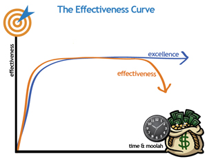
I am an engineer. BFG is an idea guy. We have been discussing this cab build on training runs (we are both training for a spring marathon), over lunch, on our cell phones on the drives to and from work, and by txt msg. On the time & money vs. excellence & effectiveness curve we have reached the middle of the plateau…

This means that spending more time (and therefore, more money) on revising the plan will not result in any better arcade cabinet. If fact, if we don’t started building the thing pretty soon we are actually getting less effective as time goes on.
So we decided to begin the build. The entire process will be documented here in way too much detail, starting with an overview of the cab plan:

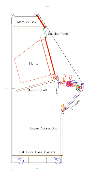
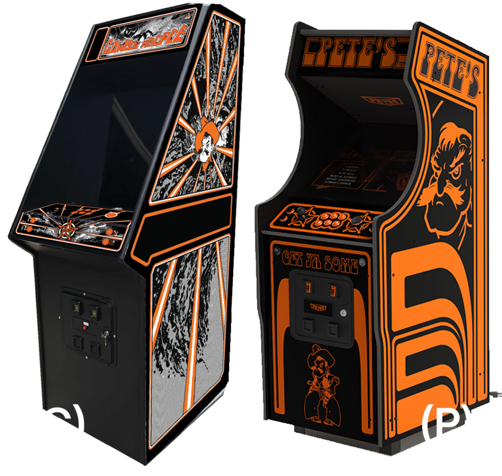
Sides: 3/4 MDF (same as all construction panels except the back) covered in formica (grade 10 black 0.048″) the sides are shaped like the famous Atari Tempest cab. The size is slightly larger, but all the angles are the same. The cab is 78″ tall, 38″ from the back to the front, 27″ deep at the base, and 28.5″ wide.
Base: recessed 3″ rubber casters should make moving the Cowboy Arcade a breeze. Extra reinforcement provides both lateral stability and should help with weight distribution.
Back: 1/4 masonite material saves weight and will be screwed into place as a means to help stabilize the cab from shifting side-to-side. Divided into two panels, the back can be removed if major service is necessary, but is intended to be “permanent”. Large slots will be milled into the bottom and top to create air flow.
Lower Access Door: main access to the computer. Hinged on left and barrel lock on right. No Coin Mech.
Control Panel: the CP sits on the supports that are permanent. It is trapped at the back and sits on pins at the front. This allows it to be easily removed without tools if necessary. This also opens the door to changing this part later. Admin buttons are located on a back panel that also acts as part of the monitor bezel structure. Plunger button and sound system controls are located on the front of the CP box and the System Shutdown and Reset button are located far down the CP Lower Panel and are recessed. Flipper and Nudge buttons are located on the cab sides.
Monitor Shelf: even though the monitor will be a Nieman monitor and therefore hard mounted by the frame in the cab, there is still going to be a permanent shelf to separate the lower portion of the box from the top. This is for safety, allowing a person to work in the lower cabinet without any danger of coming in contact with the high voltage parts of the monitor. The shelf will be slotted for air flow.
Speaker Panel: also part of the monitor bezel, the speaker panel provides a place to create the holes necessary to get the sound from the speakers (mounted somewhere in the top of the cab) out to the players. There is hope that the grills from the satellite speakers will be usable in this area.
Marquee Box: at the top of the cab, the marquee box is solid on the top, bottom and back. A hole to feed power into this space will be the only connection to the upper cab space. An LED light bar will light the marquee, which is removable, and should not generate any heat. The additional structure will make the box more rigid.
There are TONS of construction details that will be documented as the build progresses.

Leave a Reply
You must be logged in to post a comment.