Computer:
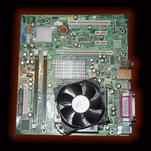
The Cowboy Arcade is powered by a decased HP computer. The basis for this computer is an MS-7336 Ver 1.0 Motherboard with an Intel Core 2 Duo E2160 Processor.

MS-7336 VER: 1.0 Motherboard Specifications.
| CPU | Intel Socket LGA775 – Support Processor Type: Intel Core 2, Pentium Dual Core, Pentium D, Celeron, Pentium 4 with Hyper-Threading Technology3 Intel Core 2 Duo Processor: E2160 |
|
Chipset
North Bridge
|
Intel 946GZ Express |
| South Bridge | Intel ICH7 |
| Integrated Graphics | Intel (GMA 3000) |
| Memory |
2 * 240-pin DDR2 DIMM slots Supports
DDR2 677/533 Dual Channel non-ECC, un-buffered memory
(Max 4GB)
|
| Expansion Slots |
1 * PCI Express x16
2 * PCI Express x1
1 * PCI
|
| Storage | 4 * SATA 3Gb/s connectors Supports HDDs, SSD |
| Audio | Realtek ALC888 – High Definition |
| Ethernet | Intel 82562xx – LAN 10/100Mb/s |
| Special Features |
* CPU Smart Fan Function
* System Fan Fail Check
|
| Rear Panel |
4 * USB 2.0 ports
1 * VGA port 1 * RJ-45 LAN port 1 * Audio I/O
1 * Serial port 1 * Parallel port
1 * PS/2 green color for mouse
1 * PS/2 purple color for keyboard |
| Internal |
1 * 4-pin CPU Fan connector
1 * 3-pin Chassis System Fan connectors 1 * 4-pin ATX 12V Power connector 1 * 24-pin ATX Power connector
1 * Floppy header
1 * Front Audio header
1 * Front Panel header 2 * USB headers
|
| BIOS | To Enter BIOS Setup: Press F10 |
| Form Factor | Micro-ATX |
Hp/Msi MS-7336 Motherboard Supports: Win 7, Vista/Xp, Ubuntu
ATX 24 pin power supply connector pinout
ATX 2.2 and later (ATX12V 2) is common ATX standard, 24 pin connector.
Changes to ATX standard were made to support 75 watt PCI Express requirements. Most power is now provided on 12 V rails and the power on 3.3 V and 5 V rails was significantly reduced. The standard specifies that two independent 12 V rails (12 V2 for the 4 pin connector and 12 V1 for everything else) with independent overcurrent protection are needed to meet the power requirements.
New ATX v 2.2 uses new connector, but most motherboards nowdays allow to use an old ATX v 1.x power supply with ATX 20 pin connector – it connects to 24 pin motherboard receptacle.
| Pin | Name | Color | Description | |
|---|---|---|---|---|
| 1 | 3.3V | Orange | +3.3 VDC | |
| 2 | 3.3V | Orange | +3.3 VDC | |
| 3 | COM | Black | Ground | |
| 4 | 5V | Red | +5 VDC | |
| 5 | COM | Black | Ground | |
| 6 | 5V | Red | +5 VDC | |
| 7 | COM | Black | Ground | |
| 8 | PWR_OK | Gray | Power Ok is a status signal generated by the power supply to notify the computer that the DC operating voltages are within the ranges required for proper computer operation (+5 VDC when power is Ok) | |
| 9 | 5VSB | Purple | +5 VDC Standby Voltage (max 10mA, max 2A in ATX 2.2 spec) | |
| 10 | 12V | Yellow | +12 VDC | |
| 11 | 12V | Yellow | +12 VDC | |
| 12 | 3.3V | Orange | +3.3 VDC | |
| 13 | 3.3V | Orange | +3.3 VDC | |
| 14 | -12V | Blue | -12 VDC | |
| 15 | COM | Black | G | |
| 16 | /PS_ON | Green | Power Supply On (active low). Short this pin to GND to switch power supply ON, disconnect from GND to switch OFF. | |
| 17 | COM | Black | Ground | |
| 18 | COM | Black | Ground | |
| 19 | COM | Black | Ground | |
| 20 | -5V | White | -5 VDC (this is optional on newer ATX-2 supplies, it is for use with older AT class expansion cards and can be omitted on newer units) | |
| 21 | +5V | Red | +5 VDC | |
| 22 | +5V | Red | +5 VDC | |
| 23 | +5V | Red | +5 VDC | |
| 24 | COM | Black | Ground |
/PSON activated by pressing and releasing the power button while the power supply is in standby mode. Activating /PSON connects the power supply’s /PSON input to ground, thereby switching the power supply to full-on condition.
18 AWG is recommended for all wires except pin 11, which should be 22 AWG. For 300W configurations 16 AWG is recommended.
24 pin MOLEX 44206-0007 Male connector at the motherboard:


24 pin MOLEX 39-01-2240 or equivalent Female connector at the PSU cable:


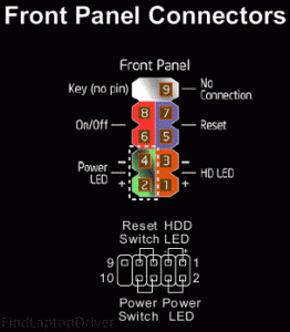
Front Panel Connectors:

ATX / BTX +12V power connector:
| Pin | Name | Color | Description | |
|---|---|---|---|---|
| 1 | COM | Black | Ground | |
| 2 | COM | Black | Ground | |
| 3 | +12VDC | Yellow | +12 VDC | |
| 4 | +12VDC | Yellow | +12 VDC |
4 pin MOLEX 39-29-9042 connector at the motherboard:

4 pin MOLEX 39-01-2040 connector at the cable:

The SATA Connectors:
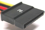
The SATA standard specifies a power connector sharply differing from those used by PATA drives and many other computer components. It is wafer-based, 15-pin shape. The seemingly large number of pins are used to supply three different voltages — 3.3 V, 5 V, and 12 V.
Each voltage is supplied by three pins ganged together (and 5 pins for ground). This is because the small pins cannot supply sufficient current for some devices. One pin from each of the three voltages is also used for hotplugging. The same physical connections are used on 3.5-inch and 2.5-inch notebook hard disks.
| Pin | Signal | PSU Color Wire | |
| 1 | +3.3VDC | orange | |
| 2 | +3.3VDC | orange | |
| 3 | +3.3VDC | orange | |
| 4 | GND | black | |
| 5 | GND | black | |
| 6 | GND | black | |
| 7 | +5VDC | red | |
| 8 | +5VDC | red | |
| 9 | +5VDC | red | |
| 10 | GND | black | |
| 11 | Optional | black | |
| 12 | GND | black | |
| 13 | +12VDC | yellow | |
| 14 | +12VDC | yellow | |
| 15 | +12VDC | yellow |
Pins 3,7,13 are pre-charge.
Pin 11 can be used for activity indication and/or staggered spin-up.
Pins 1, 2, and 3 are optional as well, as evidenced by some adapter cables that connect the drives to older PSUs. These are usually Y-adapters that have the four-pin drive connector on the other end. Currently, SATA drives rarely use 3.3 volts. That may be because there are too many people using adapters so the drive makers don’t want the headaches which come with using 3.3 volts. But in the future, 3.3 volt drives may become common so you need to be careful when using SATA power cables which don’t implement 3.3 volts.
Molex 67582-0000 used for cable connector and Molex 67581-0000 used for terminals connector.
Male plug at the drive:
![]()
Female plug on the cable:

![]()